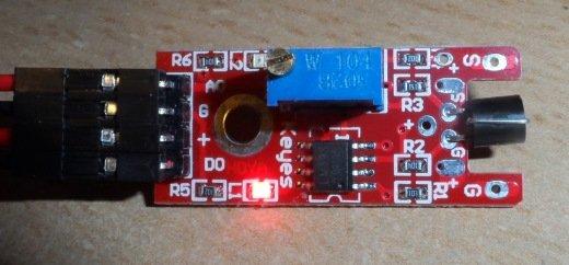
In a sensor pack we recieved recently there were a large amount of sensors but little documentation. One of the sensors that caught our attention was a touch sensor.
These are connected as follows
| Pin | Label | Arduino Connection | |||
| 1 | AO | Analog input | |||
| 2 | G | Ground (GND) | |||
| 3 | + | 5 volt power | |||
| 4 | DO | Digital input |
So a quick and easy test is to write a sketch which outputs the digital and analog readings to the serial port and then see if we can get the readings to change
Code
// Arduino pin numbers
//D2 and A0 used
const int digital = 2;
const int analog = 0;
void setup()
{
pinMode(digital, INPUT);
Serial.begin(115200);
}
void loop()
{
Serial.print(digitalRead(digital));
Serial.print(“-“);
Serial.println(analogRead(analog));
delay(250);
}
Now compile and upload this and open the serial monitor and set the baud rate to 115200 and you should see something like the following
As you can see there are 2 sets of readings
The 0 and 1023 is the reading when no touch is detected. The 1 and 113 is the reading when a touch is detected


